Proximity Switch is non-contact type limit switch. With variety of output, Ex Linear, digital, etc.
Welcome To Sai Control System
Mail Us : 
FAQ
Welcome To Sai Control System
-
1.What is Proximity Switch?
-
2.What is Sensing Zone?
The switch has dome shaped field present in front of the sensor is called as sensing zone.
-
3.What is Sensing Distance?
This is the distance between the target & the sensing face at which the switch operates.( ex. This is usually specified considering MS material as target in case of inductive proximity switch.)
-
4.What is Repeat Accuracy?
This is the accuracy whereby the switch operates repeatedly at specified point of operation given stable operating conditions.
-
5.What is Response time?
This is the time by which the switch changes its state after target enter the sensing zone. For DC switches the response time can be as low as 0.1 ms but for AC switches this is around 20 ms due to external load parameters.
-
6.What is Flush Mounting?
If switch referred to as Flush type can be mounted inside metal body and have only frontal electromagnetic field.
-
7.What is Non- Flush mounting?
These type of switch has been mounted with sensing zone in metal free area.
-
8.What is switching Hysteresis?
This is differential between “switch ON” and “switch OFF” point of bthe switch. Which helps avoiding chattering at the sensing point.
-
9.What is Output logic?
The output switching element (either a Transister or Thyristor) can be normally in closed (ON) OR open (OFF) condition. It can sink, or source, examples as below, PNP-NO, NPN-PO, etc.
-
10.What is Load Current?
This is max. Current, which the switch can either sink from or source to the external load.
-
11.What is NAMUR sensor?
The NAMUR type sensor is intrinsically safe proximity switches designed to work in the hazardous areas. The working voltage & current levels of these switches are restricted to safe values as per standards.
-
12.What is Switch with Built in timer?
The NAMUR type sensor is is intrinsically safe proximity switches designed to work in the hazardous areas. The working voltage & current levels of these switches are restricted to safe values as per standards.
-
13.What is correction Factor?
Targets other than MS actuate the inductive switches at relatively less distance with correction factor.
-
14.What is Inductive Proximity Switch?
Inductive proximity switch works on principle of damping of oscillations by conductive materials. Senses only metallic objects. It is useful for medium counting speed. It has short sensing gaps.
-
15.What is an Optical Proximity Switch?
Optical Proximity switch works on principle or interruption/ reflection of infra red beam light. Senses any opaque object from Sensing Distance with Medium counting speeds and high position sensing accuracy.
-
16.What is Sensor Probe Size?
It gives the shape and dimensional detail with mounting arrangement of the proximity switch.
Frequently Asked Questions- Regarding "TRIP INDICATION SYSTEM for Conveyor Safety"
-
1.What is the voltage required for this system?
This system operates on 24VDC and requires 1A current. It can source power supply from PLC Panel or we can provide SMPS suitable for 110 / 230 Vac as per your requirement.
-
2.What is the minimum voltage required for the system to works?
At least 9 to10 Vdc required at last switch of conveyor.
-
3.How many Master Unit require for one conveyor and how many switches it can accommodate?
Per conveyor one Master unit is required as it can provide only one trip command. Normally maximum 70 switches in series can be connected to one Master Unit.
-
4.What is the distance required between Control Room (Master Unit) and first Pull cord switch?
Theoretically there is no limit for this but it can be up to 2 KM.
-
5.Is any extra cabling required to be done on site?
No. Your existing 2 core control cable is used by this system. Only little modification required in control room to accommodate Master Unit at operator level.
-
6.Does the sensor module need any specific mounting provision inside the Belt Monitoring switch enclosure ?
NO. The sensor Module is miniature in size ( 50 mm X 28 mm X15 mm epoxy molded ) and is also light in weight hence it can be placed anywhere in the enclosure and does not require any specific mounting arrangement.
-
7.How should one assign the position numbers to switches in the field?
The switch number is entirely dependent upon the location of it in the electrical circuit. The one closest from Master controller is assigned as switch no 1. It will increment with every next switch in series. Shown below are two typical connections and corresponding numbers assigned.
-
8.How does the Master controller indicate position of faulty cable or cable breakage ?
This unique feature is very useful for maintenance engineers and is available in our all the models . If the two core cable is snapped ( electrically open ) between e.g . switch no 14 & 15 , the controller will alternating display opn 14 continuously on its display . Hence the maintenance engineer will immediately know that there is a breakage of wire between switch no 14 & 15
-
9.What is the “ cable short detection “ feature and what are its uses.?
In case of cable short then controller l display will ckt
-
10.How Sensor Modules are installed in field?
Following figure1 shows Standard Pull Cord Switches connected in series
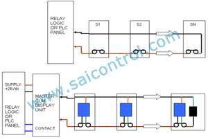
Above figure shows sensor module inserted inside Pull Cord Switch and little modification in control room cabling to accommodate master cum display unit. Sensor module has three wires, 2 wire (Red and green) connected across 'NC' contact of PCS and black wire connected to common/return wire in PCS loop Now 2 core cable from field connected to Master Unit. Master Unit is powered by 24Vdc from PLC Panel/ 24 volt power supply. Master Unit will provide Trip Contact to PLC/Relay Logic Panel. -
11.How Master Unit can recognize operated switch?
The Master controller sends a modulated signal to the Field Sensor module for finding the status of the contact of the Belt Monitoring Switch ( NC) The Field Sensor responds as per its status on the same DC line & hence the status of the Belt Monitoring Switch gets indicated on the master controller. When all the contacts are NC the display will show healthy ( hly ).and as per operation p01 / b 01 For the status of operated field switch will be displayed
-
12.What happens if more than one Pull cord operated from field?
Master Unit is capable to display more than one operated switches from field in cyclic manner.